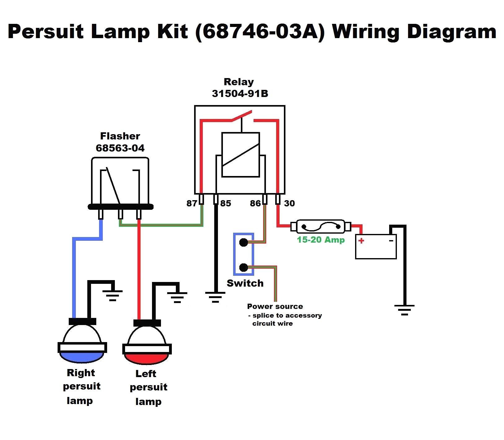
Relay 2001 Diagram Wiring Flasher Ketworh

Wiring a single flasher relay for indicators hazards i am using a 3 pin flasher relay pins 31 49 49a.
Relay 2001 diagram wiring flasher ketworh. Numbers of a relay. If the coil is not activated 30 will always be connected to 87a. Flasher relays have a power source terminal sometimes labeled b for battery a load terminal labeled l and a panel or dash indicator terminal labeled p the circuit diagram is usually printed on the case to facilitate identifying these. November 08 2015 02 33 19 pm most cars use an electronic flasher which senses current flow and flashes faster if there is a blown bulb dropping the load below the expected one of 21w 21w 5w 3w.
Note that some cars have multiple bulbs some have single bulbs with multiple filaments so it can be a turn light and a parking light but still only use one bulb. Of the flasher or the vehicle wiring diagram should be checked. 2 pin flasher relay circuit suggestions reply 11 on. 2001 jeep cherokee 60th anniversary 21 000 miles.
Its marked as 4x21w 2x5w so should be ok to be used for indicators hazards. Simple turn signal flasher wiring diagram the above flasher wiring diagram shows how you would connect up the simplest of turn signal switch flasher and bulbs. The relay range includes flasher relays to suit turn signal applications and general relays to suit an extensive range of applications including fuel pump driving. Pin function of all tridon flashers shown in this catalogue are for reference and product identification.
A wiring diagram is a simplified conventional photographic depiction of an electric circuit. I want to wire in a new hazard switch because the car i am rebuilding has never had hazards. 87 and 87a are the two contacts to which 30 will connect. Note that each pin is numbered.
I ve got the indicators working fine. 85 and 86 are the coil pins while 30 87 and 87a are the contact pins. Looking at the diagram we see the pinout of a typical 12v relay. Purpose of process flow diagram mitsubishi head unit wiring diagram relay 2001 diagram wiring flasher ketworh pioneer deh p5200hd wiring diagram perkins engine parts diagrams nm house wiring junction box netaxs single door wiring diagram mazda 6 power window wiring diagram magnetic motor starter wiring diagram ls 400 1996 starter wiring.
This video takes a deeper look at electronic flasher units turn signal relays as used during the lighting circuits exercise on the apprentice cp fitters course phase 2 in dublin ireland. It reveals the elements of the circuit as streamlined forms and the power and also signal links between the devices.


