Red Jacket Well Pump Wiring Diagram Electric

Wiring Diagram For 220 Volt Submersible Pump Well Pump Well

How To Control A Lamp Light Bulb From Two Places Using Two Way

2 Wire Vs 3 Wire Well Pump Motors Youtube

Need Wiring Diagram Verification Terry Love Plumbing Advice
2018 New Red Jacket Endure 1hp 2hp Big Flow Gasoline Submersible

Wiring Diagram For 220 Volt Submersible Pump Well Pump

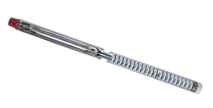
Part of the industry s leading veeder root suite of products red jacket s family of submersible turbine pumps stps and pump controllers ensure that your customers can pump fuel quickly efficiently and safely whether it s motor fuel diesel aviation gasoline ethanol methanol or kerosene.
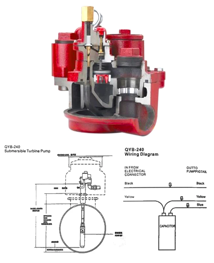
Red jacket well pump wiring diagram electric. 3 94 3 75 w ater pumps from red jacket are the natural choice of well drillers pump installers and home. Replace the cover on the pressure switch after the zero voltage check and move to the pump control box further downstream. Collection of 3 wire submersible pump wiring diagram. It shows the elements of the circuit as simplified forms and also the power as well as signal links between the devices.
Service spill elimination. To replace and reconnect a three wire pump. It shows the components of the circuit as streamlined shapes and also the power and also signal links in between the devices. A wiring diagram is a streamlined traditional photographic representation of an electrical circuit.
A wiring diagram is a streamlined standard photographic representation of an electric circuit. Newly designed features of the red jacket stp are. The red jacket stp fits 4 inch npt threaded thin wall risers and is available in a wide variety of horsepowers. To order a complete pump and motor assembly combine the motor order number followed by the pump water end order number.
Red jacket s unsurpassed expertise helps your customers optimize fuel flow. Replace a three wire pump. In this video i go over the differences of a 2 wire and a 3 wire submersible well pump this is associated with the starting components for the pump and whether they are located inside the motor. Red jacket line leak detection systems do not function if the submersible pump runs continuously.
In this video we address how to properly set up a motor with a jet pump and how to overcome some common challenges when installing or troubleshooting a motor. Most boxes will only show designator marks y r b l1 l2 denoting the pump and incoming wire placement but they may have faded. A 50c3116g17 a hp 230v 3 wire centripro motor on a 6g17 water end. Collection of well pump pressure switch wiring diagram.
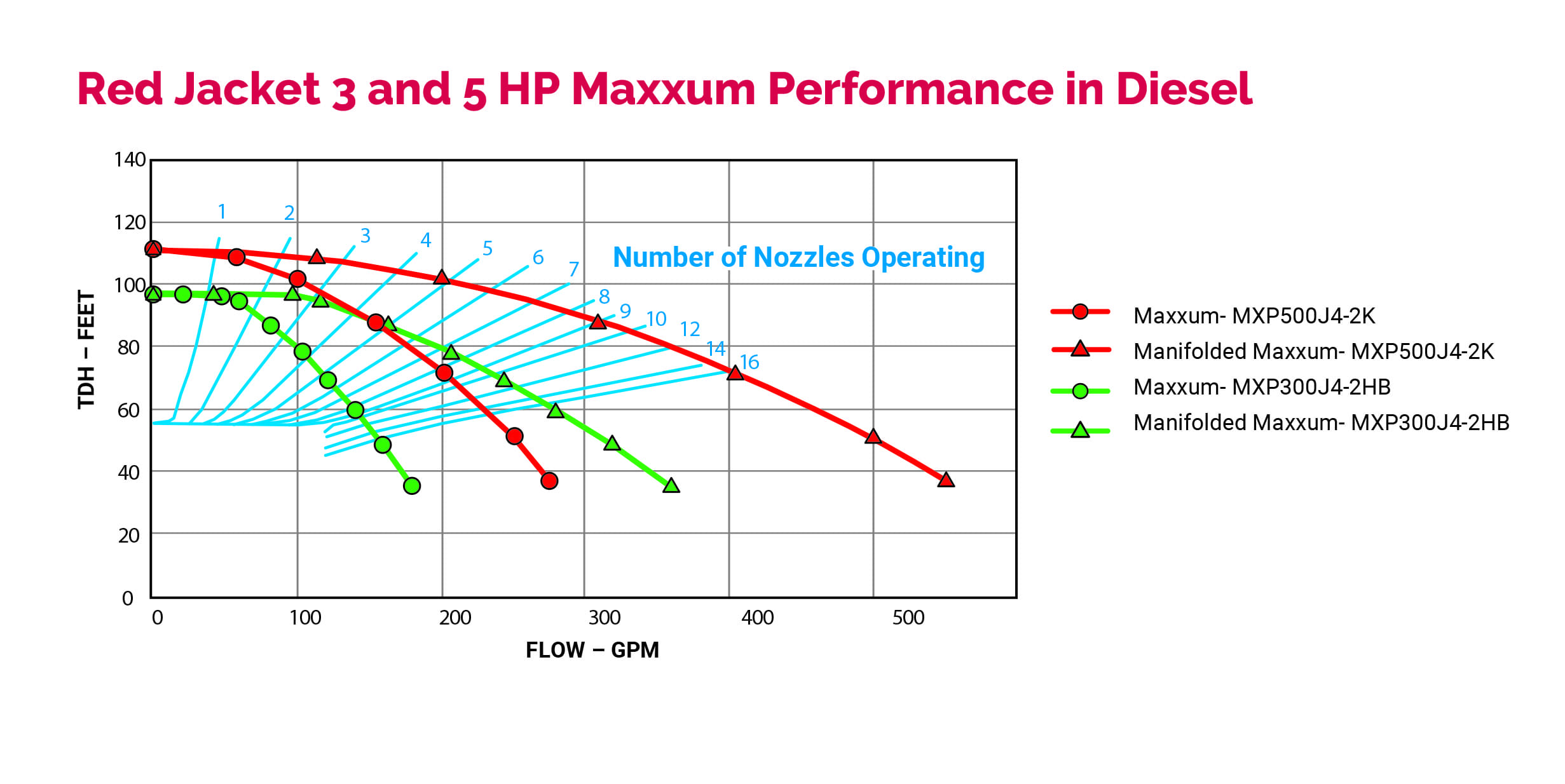
The units are designed to operate continuousl y at or above minimum flow rate or with an intermittent duty cycle not to exceed 20 on off cycles per hour. The red jacket submersible turbine pump stp is engineered for advanced environmental protection serviceability safety and flow.

Red Jacket Check Valve Lock And Release Youtube

12 Awesome Wiring Diagram For 220 Volt Submersible Pump Ideas
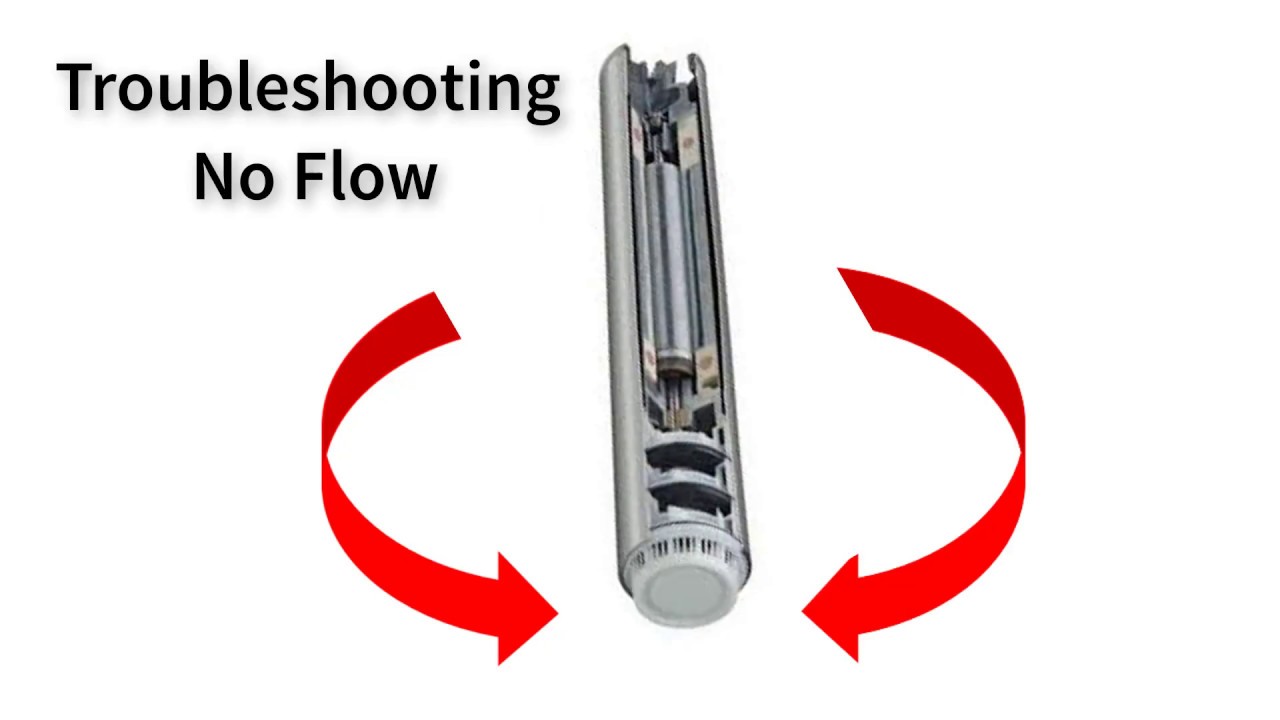
Red Jacket Ump Quick Troubleshooting Guide No Flow Youtube

Submersible Well Pump Wiring Diagrams Lovetoknow

Single Phase Motor Wiring With Contactor Diagram With Images
Red Jacket Maxxum Submersible Turbine Pump Stp Veeder Root

How To Replace Jet Pump Pressure Switch Change Voltage Youtube

Red Jacket Submersible Turbine Pumps Built To Last Youtube

17 Basic Car Electric Fuel Pump Wiring Diagram Car Diagram In

Heat Wiring An Spdt Thermostat To Simultaneously Control Heating

1998 Jeep Cherokee Fuel Pump Wiring Diagram Google Search In

16 Ac Electric Drill Wiring Diagram Wiring Diagram In 2020

Split Ac Wiring Diagram Image With Images Ac Wiring