Red Jacket Pump Control Box Wiring Diagram

Wiring Diagram For 220 Volt Submersible Pump Well Pump Well

Need Wiring Diagram Verification Terry Love Plumbing Advice

How To Control A Lamp Light Bulb From Two Places Using Two Way
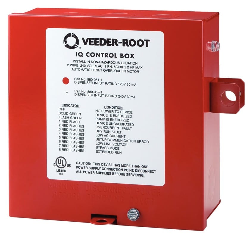
Red Jacket Lpg Premier Stp Veeder Root

Wiring Diagram For 220 Volt Submersible Pump Well Pump

Heat Wiring An Spdt Thermostat To Simultaneously Control Heating

Collection of submersible pump control box wiring diagram.
Red jacket pump control box wiring diagram. It shows the elements of the circuit as simplified forms and also the power as well as signal links between the devices. Red jacket s standard control box with 115 vac coil for all single phase 1 3 1 and 2 hp motors is the simplest way to control site fueling. The red jacket standard control box is the simplest way to control site fueling. Red jacket iq smart controller box.
Demanded more than one pump per tank. Collection of 3 wire submersible pump wiring diagram. The first control box fell off the wall and stopped working. In this video chris shows you how to wire the franklin electric qd control box.
The red jacket submersible turbine pump stp is engineered for advanced environmental protection serviceability safety and flow. How to wire a submersible pump controller. A wiring diagram is a streamlined traditional photographic representation of an electrical circuit. Maintain safe reliable efficient fuel flow with red jacket s most basic submersible turbine pump interface.
All 3 wire submersible pumps from 1 3 up to 1 hp utilize a qd control box to start the pump. Maintain safe reliable efficient fuel flow the red jacket s most basic submersible turbine pump interface. It shows the elements of the circuit as streamlined forms and the power and signal connections in between the devices. Red jacket s iq control box can be connected to additional control boxes to allow up to four pumps per tank with demand driven sequencing.
Suggested wiring diagram without optional control box. Wiring power from the panel to the red jacket stp. The standard control box interfaces between the fuel dispenser and the turbine pump and has an indicator light that signals when a customer begins fueling. The wires are the same as the orginal red jacket and we wanted to check to see if there was a compatible issue with the new box before we pulled the pump.
A wiring diagram is a simplified traditional photographic depiction of an electrical circuit. This function can be set to alternate between pumps that initiate next dispensing events to average the wear on all of the pumps in the system.

2 Wire Vs 3 Wire Well Pump Motors Youtube

Single Phase Motor Wiring With Contactor Diagram With Images

Red Jacket Submersible Turbine Pumps Built To Last Youtube
Http Www Saltech Co Il Uploads Dbsattachedfiles Manual Dp Dq Dr Ds Dt English C133292 Sflb Ashx Pdf
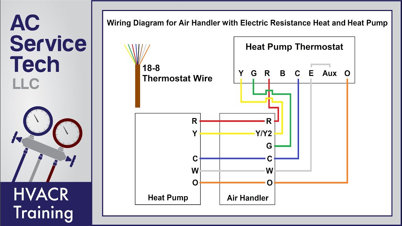
Heat Pump Thermostat Wiring Explained Colors Terminals

Badlands Winch Wiring Diagram Winch Warn Winch Wire

Volvo Penta Fuel Pump Wiring Diagram Yate Motores

1998 Jeep Cherokee Fuel Pump Wiring Diagram Google Search In

Meyer Snow Plow Parts Diagram Meyer Wiring Diagram Meyer Snow

Eg Fuel Pump Wiring Diagram
Manual Auto Aerator Switch Page 1 Iboats Boating Forums 602460

Gilbarco Electricalwiring Electrical Wiring Equipment

Installing A Pressure Switch And Power Cord On A Centrifugal Pump
